Table Of Content
- Systematically use models throughout your development process
- What is Model-based Development?
- DESIGN AND AUTONOMOUS TESTING OF A LOWER LIMB PROSTHESIS
- Introduction to Model-Based Design: Modeling and Simulation with Simulink
- Scalable Fabrication of Organic Single-Crystalline Wafers for Reproducible TFT Arrays
- An Introduction to Model-Based Systems Engineering (MBSE)
The MVLR model provides information about the interplay but is not suitable to predict the microstructure with high accuracy. It may rather provide an estimate about the spatial extent in context to the microstructural feature space. For the definite reconstruction of the microstructure, we utilize a conditional GAN (cGAN) model and diffusion-based model (DDPM). The work highlights how a cGAN and DDPM architecture renders possibilities for the reconstruction of synthetic microstructure images.
Systematically use models throughout your development process

Not only does this make MBSE more efficient than traditional methods, but it can add clarity, reduce the risk of error and improve communication and decision-making among engineering teams and other stakeholders. This enables information consistency throughout all lifecycle phases of the project. Reduce the risk of slowing down development by introducing Model-Based Design in stages.
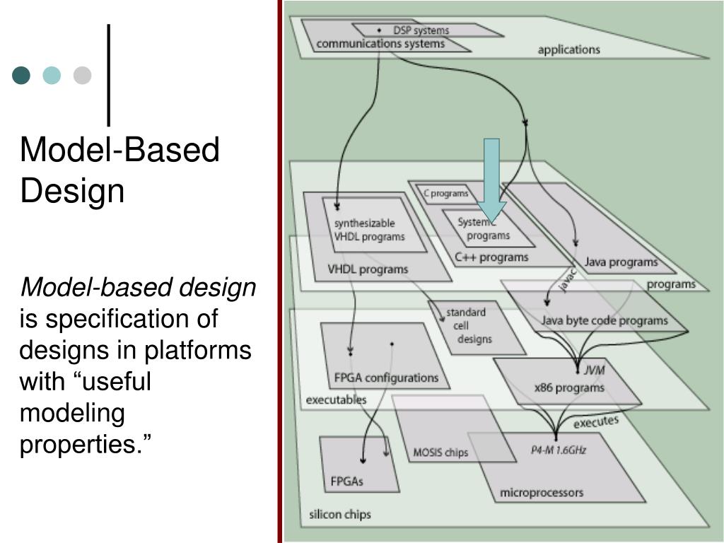
What is Model-based Development?
Model-Based Design enables fast and cost-effective development of dynamic systems, including control systems, signal processing systems, and communications systems. Software-in-the-loop testing is the second stage of verification and validation. SIL tests occur after the engineer has generated code from the control model. The goal is to detect errors in the auto generated software code and resolve them. It involves running the generated C code on a local computer and the comparing the results to the MIL test.
DESIGN AND AUTONOMOUS TESTING OF A LOWER LIMB PROSTHESIS

Figure 4a shows the resulting minimum power consumption that is required to reach different clock frequencies, up to 454 kHz. It is unfair and not necessary to directly compare both chips because of the absence of a complementary semiconductor in IGZO and more importantly because of the different application cases for both technologies. Nonetheless, both of them are fully functional and show predictable specifications related to their underlying transistor technology.
For example, simulation can be used to verify a design of a system and optimize the hardware and software implementation before its construction to avoid potentially expensive physical prototype iterations. The next step is to assess the quality of the reconstructed synthetic images. As illustrated here16, Frechet inception distance (FID) as well as precision and recall are not suitable to measure the quality of synthetic microstructure data.
SCADE and Simulink tool suites are both highly intuitive to work with because you primarily use diagrams and graphical programming to build models instead of manually writing code. If you need to add or edit code manually, most environments give you the option to do so. If you are stuck on a particular model, you can easily create a temporary build to debug roadblocks. You can also run simulations of the model alongside the compiled versions of the software build.
Fabrication of carbon nanotube field-effect transistors in commercial silicon manufacturing facilities
Here, we assesses the quality of the synthetic images based on extracted physical descriptors of the microstructure or microstructural features57. A Prediction results for MVLR model A, C and I versus the measured electrical conductivity. Here a linearity is provided from 10 to 200 uS.cm−1, which is not for the whole experimental window. We validate the models’ performance with three test sets, indicated by Test A, C and I, not used for the training, to find the best model. B Improved prediction results for model J, N and R incorporating the engineered feature α in combination with raw features.
Scalable Fabrication of Organic Single-Crystalline Wafers for Reproducible TFT Arrays
ISE welcomes new faculty with model-based systems engineering focus - Auburn Engineering
ISE welcomes new faculty with model-based systems engineering focus.
Posted: Fri, 11 Aug 2023 07:00:00 GMT [source]
However, the extremely low-leakage current of IGZO transistors20,23 creates innovative opportunities in circuits, especially for memory. Capturing system attributes in models enables systems engineers to perform threat-modeling analysis of the system early and incorporate mitigation strategies into the system design, thereby reducing the system's overall security-related risks. A physical system as it exists in nature, on the testbench, or within an application is usually defined as a set of interconnected and interacting objects or components which perform a task or variety of functions. In model-based design, it is implied that a physical system is the study of the mechanisms inside a system using fundamental physical laws and engineering principles. A model, as it exists within a physical system simulation environment, reflects a selected object or component, indicating it is an approximation.
For the evaluation of the copper strut diameter ϕ and its evolution upon sintering, we skeletonize and statistically analyze the segmented data24 (Fig. 2d, e). The mean values are obtained by fitting the log-normal distribution of the strut diameter histograms (Supplementary Note 4). This behavior is linked to the continuous growth of the bonds between the sinter particles due to the increase in temperature45. The NPC material indicates a small variation of the copper strut diameter. The 95% confidence interval lies within a range of 0.01–3.5 nm and suggests a highly homogenous distribution of the copper network as indicated for the volumetric microstructure data in Fig.
D The complexity of the sintering process is illustrated by joint distributions of the Gaussian (G) and mean (M) curvatures. All materials’ tails stretch in the first quadrant (QI) and second quadrant (QII). The QI tails show the presence of small radii convex regions, inversely related to the magnitudes. Consequently, the low temperature plots show the early stage of sintering. In contrast, the QII tails show the progress of sintering when the particles are joining.
Model-based design of gradient elution in liquid-liquid chromatography: Application to the separation of cannabinoids - ScienceDirect.com
Model-based design of gradient elution in liquid-liquid chromatography: Application to the separation of cannabinoids.
Posted: Thu, 25 Apr 2024 01:16:51 GMT [source]
The user of the model should be able to see clearly how the top-level concepts and components decompose to the lower level features. Users should be able to perform system analysis, create dependency matrices, run simulations, and produce a view of the system for every stakeholder. If the physical part of the system must change, the logical side of the model identifies exactly what functionality will be affected. If a requirement or business process must be changed, the model will easily discover the impact on the solutions. It requires its own actors, processes, environment, and information flows. To create a successful model of a complex system or system of systems, an organization must support the modeling process.
It is because MBSE allows for the clear, open representation of intricate relationships and dependencies within a system. MBSE reduces the risk of errors and inconsistencies, which are common in document-centric systems, by allowing greater traceability. Models provide a single source of truth, ensuring that all stakeholders are working with the same information and can identify system-level issues quickly.
A, d and g illustrate the segmented microstructures for the porous materials HPA, HPB, and NPC obtained with FIB-SEM. B, e and h correspond to the predicted (synthetic) microstructures utilizing the cGAN model for HPA, HPB, and NPC, respectively. The data visualized in c, f and i correspond to the predicted (synthetic) microstructures utilizing the DDPM for HPA, HPB, and NPC, respectively. The synthetic and experimentally retrieved (real) microstructures are plotted for different sinter temperatures. The segmented copper and pore phases are illustrated in white and black, respectively.
The next step involves selecting the right software tools and technologies that support MBD, as well as providing comprehensive training and support to employees to enable smooth adoption. The company should establish clear standards and processes for creating and managing 3D models, including annotation, GD&T, and other product specifications. Defense Acquisition University defines digital engineering as an integrated digital approach that utilizes authoritative systems and models throughout a product’s lifecycle. For a more simple definition, MBSE is essentially using software tools to build models and simulations of new software. For the past two decades the aerospace industry, specifically commercial aerospace, has utilized a model-based approach for embedded software development and testing. Companies gradually adopted this method due to the many advantages provided by this kind of software development and its strengths over traditional or legacy software development.
Lastly, a case study from Springer describes how MBD was used to replace datasets of models and drawings, creating a “single source of truth”. Additionally, a case study from Capvidia describes how MBD was used to improve process efficiency, reduce rework, create better products with faster time to market, and improve communication between departments. Model-Based Definition facilitates seamless integration between different suppliers involved in the manufacturing process. By sharing the 3D model, suppliers gain a comprehensive understanding of the design intent and can provide more accurate quotes, reducing the back-and-forth communication and improving collaboration.
To compare the performance and power consumption metrics of both inverter architectures, 19-stage ring oscillator circuits are designed and characterized (Supplementary Fig. 3). Figure 2c shows the oscillation frequency values with respect to VDD supply, in which VBIAS equals twice VDD for pseudo-CMOS. The CMOS inverter can achieve a stage delay lower than 1.5 ns when operated at large supply voltages. The oscillation frequency of those ring oscillator inverters is plotted versus the power consumption in Fig.


No comments:
Post a Comment